Underfloor Radiant Heat Systems
Our Heat Transfer Plates are Made in the USA!
Notice how the Heat Transfer Plates are shaped to fit the perimeter of the tubing.
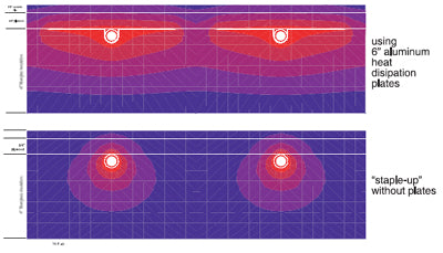
Heat transferred from the tubing to the trough portion of the heat transfer plate conducts out along the “wings” of the plate. Because aluminum is an excellent heat conductor, these relatively thin plates can disperse across the floor almost as well as a slab yet at a tiny fraction of the weight and only about 1/2 the added floor height of a thin-slab. They are a versatile component both for floor heating systems as well as radiant walls and ceilings.
Above Floor Tube & Plate Systems
Here the tubing and plates are located on the top side of the floor deck. The tubing can be run in virtually any direction. The system can be adapted to several types of finish flooring, and is particularly well suited for nailed down wood floor installations.
Begin by fastening 5/8” - 3/4” plywood or oriented strand board (OSB) “sleepers” to the floor. The sleepers are placed to create 3/4” wide grooves into which the tubing and trough portion of the plates are recessed. To minimize any squeaks, the sleepers should be glued as well as nailed (or screwed) to the subflooring.
Grooves for the return bends, as well as other curved tubing paths can be formed by routing out the 3/4” plywood or OSB. Another way is to place triangular shaped spacers to support the secondary floor layer at curved areas.
The plates are set into the grooves with ends spaced about 1” apart. Pull each plate against one edge of the sleeper and tack it in place with two or three light gauge staples on the same side (and only on this side). This allows the plate to expand as the tubing is pushed into it as well as when the plate heats and cools.
Then tubing is laid out and pushed into the grooves in the plates. Stepping on the tube as it aligns with the grooves ensures it is pushed all the way into the groove.
Above floor tube and plate systems are ideal when nailed-down wood flooring will be installed. The flooring can be placed directly over the tube and plates without needing an additional cover sheet. The flooring should be installed with its long dimension perpendicular to the tubing. Nails can be driven through the heat transfer plates, through the sleepers and into the subfloor. Be careful not to drive nails through the tubing on return bends or other areas when the tubing is not visible as the flooring is laid. If the tubing needs to run parallel to the flooring at times, it is best to drill a shallow hole through the subfloor and route the tubing through the floor framing where it is protected against nail punctures. The tubing can also be “plunged” beneath the subfloor and then routed up through the bottom plate of a partition to connect to the manifolds.
For other types of flooring, it is necessary to install a thin 1/4” or 3/8” cover sheet over the tube and plates to serve as a smooth stable substrate. Plywood is often used as the cover sheet under vinyl flooring or carpet. Cement board has also been used under ceramic tile. All tubing circuits should be pressure tested prior to installing the cover sheet. The tubing should remain pressurized as the cover sheet is installed. Be careful not to drive fasteners through the tubing when securing the cover sheet.
The same concept of the sleeper system can be used in low heat load installations, but without the heat transfer plates—mostly for floor warming systems.
The wood structure is a poor conductor of heat so there is limited heat transfer sideways. The relatively thin layer directly above the pipe will allow a lot more heat through than sideways. This results in large local temperature differences depending on the position of the pipe. This effect limits the amount of heat that can be transferred without creating high temperature “lines” on the floor surface.
The spacing used should be 6”-8” and again only a limited amount of heat output can be provided. To overcome this limitation, some manufacturers produce pre-routed plywood sheets with aluminum layer attached to it to improve sideways transfer.
Below Floor Tube & Plate Systems
It’s also possible to fasten the tubing and aluminum heat dispersion plates against the bottom of the subfloor. Below floor tube and plate systems work well when raising the floor level is not an option.
The plate cradles the tubing against the subfloor as well as disperses the heat across the floor to avoid objectionable variations in floor surface temperatures.
The ideal installation conditions for this system would be completely unobstructed floor joist cavities. However this is often not what the installer has to deal with. In some cases, plumbing, electrical, ducting or other utilities may already be routed through the joist cavities. This could make access to the underside of the subfloor difficult or even impossible.
Always inspect the underside of the floor deck before committing to a below floor tube & plate installation method.


